Historical of the hydraulics and the hydrodynamics
Ludwig Prandtl brought together in 1905 the hydraulics and the hydrodynamics, two disciplines of fluid mechanics which had been developed independently from each other,
The hydraulics is the experimental and user-oriented fluid mechanics, which is needed by engineers to solve practical problems. The assembly of a
hydraulics or flow network is based on the empirical pressure loss coefficients from Bernoulli; this method is also called 1D-CFD (Computational Fluid Dynamics).
The hydrodynamics is a field, in which physicians, mathematicians, and developers of flow software are mostly theoretically engaged. They analyze and
develop solving schemes for the complex non-linear flow equations from Navier-Stokes.
1D Flow networks compared to 3D CFD flow simulation
The hydraulics is the design tool for a wide range of industries and applications. From the concept phase, users can quickly conceptualize fluid system designs with minimal geometric data and evaluate design
alternatives against performance targets. The cooling system of a large installation is too big and too complex, in order to be completely analyzed with 3D simulations.
It is best practice to calculate it with the hydraulics formulas; this method is called 1D CFD or flow network and unlike the 3D simulations, a 3D CAD geometry is not required.
This method is for example used for the engineering of combined cycle and coal thermal power plants: for the water-steam cycle, the closed-cooling water system, lube oil distribution systems as well as other balance of plant systems.
As the flow calculation is an approximation, a multitude of conditions can be simulated: gas and fluids,
stationary or time-dependent, closed or open system, compressible or incompressible flow, heating and cooling as well combustion and multi-phase flows. These networks can be programmed in Excel, Fortran or in any programming language.
New networks tend to be developed with thermo-fluid sub-system software based on 1D system simulation like FloMASTER, Amesim, SimulationX.
Pressure losses in the pipeworks
Since there is no general theoretical formula for calculating the pressure losses, we are still largely dependent on experimental investigations and the hydraulic formula derived from them.
The pressure losses due to friction in straight pipes can be calculated using the pipe friction coefficient
l. It is a dimensionless coefficient,
which can be read on the Moody diagram as a function of the Reynolds number Re. This number should also be increased depending on the mean roughness.
The pressure losses due to geometry changed like pipe fittings, throttles, obstructions, entry in the pipe, exit of the pipe are added to the pressure losses due to the friction in straight pipes. These pressure losses are calculated using the coefficients of
local fluid resistance, which can be found in the literature.
The pipe system is to be installed in a predefined space, therefore the arrangement of the pipes and components must be checked using a CAD model after the hydraulic design of the system.
Pressure generation with pumps and fans
A fan is defined by its fan curve and its rotational speed; only the fan load (pressure generation and volume flow) has to be evaluated, to choose the corresponding fan in a fan catalog.
A pump conveys fluids; it is defined by its pump curve and head. If the system contains heat exchangers, then their cooling might necessitate the design of
the corresponding fans as well.
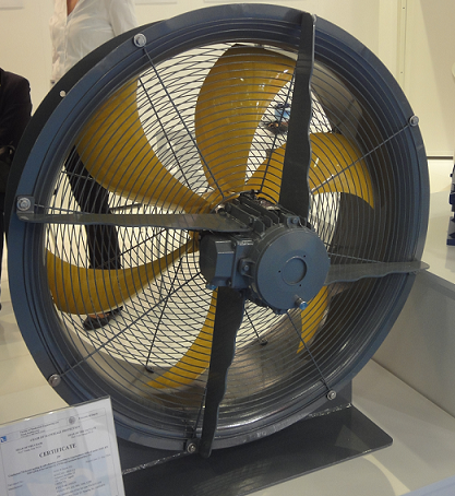
Axial fan
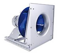
Radial
fan ER..C © Ziehl-Abbeg
Software for 1D system simulation
The 1D system simulation is the calculation of the overall system with electrical, hydraulic, pneumatic, and mechanical subsystems connected to a schematic overall system model.
These functional blocks are connected to each other by dragging and dropping them onto a sketch plane, like electrical schematics.
These tools differentiate each other in the components library, where elements like pumps, fans, valves, bends, and junctions are predefined. Passive components like heat exchangers are defined by a constant or flow-dependent pressure drop.
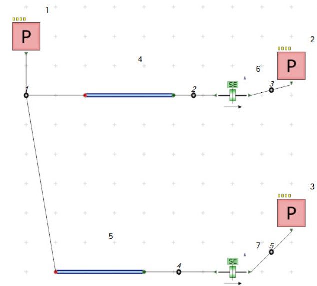 Small flow network generated with FloMASTER