Consulting for CFD Flow & Thermal Calculations
Power electronics are the key component ensuring efficient and sustainable electric production and consumption. They are used to adjust renewable energy sources like wind power stations and photovoltaics to the grid frequency or to set the inverter frequency for the speed control of a drive train.
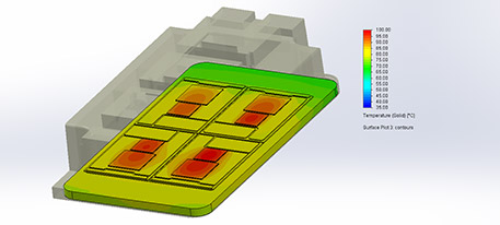
Temperature-related problems like thermo-mechanical stresses are the greatest threat to reliability. Exact compliance with the limit temperatures of the chips is mandatory; otherwise, the life expectancy will be dramatically shortened. Efficient cooling is indispensable in order to achieve the highest power density with the least amount of space. Semiconductors such as, diodes, IGBT, and MOSFET are mostly combined in compact power modules.
To dissipate the produced heat losses, the power modules are generally installed on common heatsinks. A conducting base plate can be placed between the modules and the heat sink in order to spread the heat transversally. Passive heatsinks are designed to function without a fan: the free convection flow will evacuate the heat. Active heat sinks have an electric-driven fan, and the cooling takes place by forced convection. Heat sinks are usually made of aluminum and have a very low thermal resistance. If heat sinks are not enough, the heat can be removed by a water-cooling system or even heat pipes. All these cooling methods can be well calculated with 3D CFD.
When assembling the power module to the heat sink, small air bubbles remain, which greatly increase the thermal resistance. A thermal interface material in the form of a gap pad or thermal paste is therefore used. For practical cases, it is unclear how the TIM is filled and compressed; the resulting thermal resistance is roughly estimated, resulting in an additional imprecision of the thermal calculation. The best practice is to measure the thermal resistance, which should be used as input for the calculation.
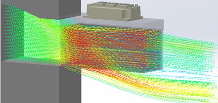
Streamlines through the heat sink of an IGBT power module
The cooling of the power electronics is so important that it should be sketched as early as possible during the concept phase. The 3D Computational Fluid Dynamics is the ideal tool to precisely
analyze the temperature and flow field; hot spots can be localized and eliminated. It is possible to obtain fast and effective computational results.
These will make viewable optimization potentials which can then be achieved with further thermal simulations.