flow and heat source networks
The first networks have been developed in the 1960s and '70s by large electrical machines companies such as Siemens Dynamowerk in
Berlin as an analogy to the electrical circuit. The network is also called an analytical lumped circuit or cluster; the thermal
network is also called heat source network, system-level thermo-fluid tool and in German Wärmequellennetz. The technique involves discretizing the model
domain into sections; each section is represented by a flow or a temperature node. These nodes are interconnected in a circuit made of several branches in
which the flow or heat transfer is moving one-dimensionally in a defined direction. Flow and thermal networks are fast tools that neither require a 3D
CAD model nor 2D drawings. Flow network calculations should be performed already in the tender phase to sketch the cooling concept and select the fan design. They can be
developed separately; in this case, the flow parameters are inputs of the thermal network; they can also be combined in one program.
We recommend developing the tool either by programming in Fortran or by using
the commercial tool FloMASTER, Amesim, SimulationX ...
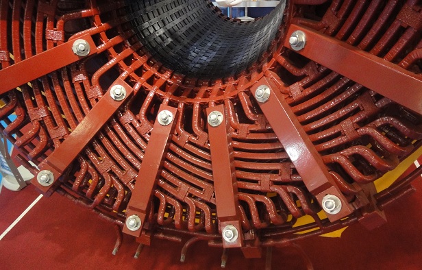 Stator coil end with distributed winding
Developing a flow network requires a high level of experience based on measured values of flow models and
machines in order to input the pressure loss coefficients and the active pressure generating coefficients. The main tasks of the
flow network are the calculation of the pressure drops and average flow velocities to design the fan system, calculate the windage losses as well as
the detection of abnormal operations like reverse flows.
Developing a thermal network requires a high level of experience and measured values, especially for the input of the heat transfer coefficients α, heat conduction
values of the laminated iron core, and coil insulation. Electrical losses, ventilation losses, and flow distribution are further inputs.
3D CFD flow calculations
The flow and thermal processes in a large motor or generator are highly complicated and they cannot be described in detail by flow and heat source
networks. Measurements inside a fast rotating rotor are very complicated due to the high circumferential speed. 3D Computational Fluid Dynamics is the correct
alternative for the analysis, concept and detailed design of electrical machines. For a cooling medium working under normal pressures, the calculation will be equally difficult regardless of whether the medium is air, hydrogen, water, or oil.
CFD allows to predict the flow structure around the stator coil ends,
the distribution of the cooling medium, pressure losses as well as temperature distribution. Using these results, the optimization potentials of the initial design
are visible. The optimum cooling should be ensured and realized with additional CFD calculations.
Symmetry
Depending on the ventilation concept, the model can be reduced to a smaller extent by using symmetry. The air enters from both sides of
the machine for dual ventilation, the model can there be reduced to half as the definition of symmetry conditions extends the machine to its full size.
Fans and wandage losses
FloEFD allows the definition of the inlet conditions through the input of the fan characteristics (dependency between mass flows
and pressure generation, inside and outside diameter, rotational speed); the operating point
is then calculated by the tool, Losses due to friction and turbulent dissipation are calculated in the place of production by the CFD tool.
The windage losses of self-ventilation machines can be determined using the fan torque.
3D CFD thermal calculations
The electrical losses are usually known as calculated or measured values; they can be allocated homogeneously in the places of production.
A conjugated thermal and flow calculation of the coiler head of a distributed winding is without simplified assumptions for winding geometry only possible with
a cartesian mesh tool like FloEFD.
 Pressure field in the air gap of Synchrongenerators with pole salients